|
A RUGGED MOTORIZED SATELLITE ANTENNA TRACKING SYSTEM FOR CONSTRUCTION BY THE HOME HANDYMAN Following numerous requests for details of my home brewed satellite tracking system I have finally got around to writing an article on it, with a photograph or two, hoping it's of interest to others. It has been in operation now since 1993 and for several of those years going 24 hrs a day monitoring the 9600 bd birds with virtually no problems Although I am using a "Sattrak 3" tracking computer to automate the tracking, the basic mechanics that I will describe can be adapted to most methods of control that use electric motors.
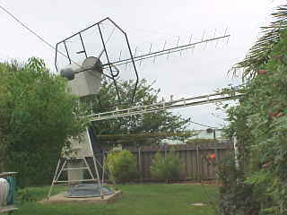
Provided that your QTH. is not surrounded by high trees or multi-story buildings I would consider this an ideal Sat. antenna system for the following reasons. POINTS IN FAVOUR 1. No high tower required. 2. Every thing can be worked on from the ground with the aid of a good stepladder. 3. Antennas can be changed with relative ease. (allows you to compare antennas easily ) 4. Less problems in high wind areas 5. Far more rugged than most commercial satellite rotator systems available 6. 12 volt operation. 7. Cheaper that commercial units of comparable strength. 8. A lot of satisfaction when completed POINTS AGAINST 1. Not practical in areas adjacent to high rise buildings or large trees 2. Requires a larger area in the back garden, typically a 10m. Diameter circles with no shrubs or buildings much above 2m. Within this area. TOOLS REQUIRED It is assumed that the constructor has a reasonable knowledge of mechanics and has a welder, angle grinder and drills etc. at his disposal.
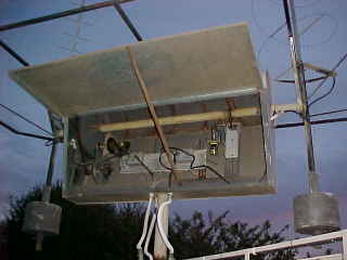
CONSTRUCTION In the construction of my antenna system I used some materials that happened to be on hand to save extra cost, so don't be afraid to change things a bit if you are in the same position. Also use the diagrams and photos as a guide with the text. Main tower Assembly. The main tower assy. is built of 1" water pipe, it is four legged and shaped like a pyramid with a flat top. The base is 1.5m square, tapering to 300mm. Sq. at the top and is 4m. high. The top has a 300mm square x 3mm thick steel plate welded to it, in which a 31/2" inside diam. collar is welded to form a bush bearing to take the vertical shaft, which is approx 33/8" O/S diam. The sides of the "tower" are covered with 22# iron from the top to approx. half way down to protect the drive from the weather. Although the "tower" is only 4m. high I found it necessary to weld cross braces to it, as it was flexing, this being caused by inertia when the Az. drive was starting and stopping. I also attached a ladder to one side to make it easier to service the El. drive and pre-amps which are located in the rotating elevation head assembly. Elevation Head Assembly. The main vertical shaft is made of thick walled tube approx. 3 3/8" o/s diam. The bottom end has a piece of 11/2" diam. shafting 300mm long welded into it to take the bull gear and a 11/2" ball bearing race on the bottom that takes the thrust. On the top of this 3 3/8" vertical pipe shaft is attached another piece of 3 3/8" pipe at right angles. This is 1.6m. long and is welded in the middle to the vertical shaft to form a "T", this forming the main horizontal support for the head assembly. On both ends of the horizontal support weld 700 mm. of 100 x 3mm. thick channel section extending upwards. Weld into each of these 75mm. from the top a bush around 70mm. long and large enough to take the horizontal pivot shaft which is made from 2" water pipe. These 2 bushes as well as the vertical one should have grease nipples fitted as the shafts are exposed to the weather. This whole head assembly is enclosed with iron; the top rounded section was made from a 44-gallon drum cut down the middle end on, and joined together. One side panel is hinged from this to allow access to the elevation drive and pre amps etc. (See photos).
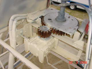
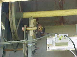
Drive Motors and Gearing. The ideal speed for tracking is around 1 revolution per min for both El. and Az. drives so a reduction is required. The two drive motors are Bosch windscreen wiper motors, ex. the local car a wrecking yard. Make sure that you get ones with a permanent magnet field, as it is only necessary to reverse the voltage to get a reverse rotation with these. AZ. Drive - Version 2. I rebuilt the AZ drive back in 2003 replacing the old cast gears with a machined crown wheel and pinion from a discarded International tractor, the crown wheel measures 32 cm. diam and the pinion approx 10 cm. diam. giving a 3:1 reduction. The pinion is fitted to a worm drive gearbox with a 25:1 ratio that's driven direct-coupled to the windscreen wiper motor. This new drive system has done away with the dual chains and has virtually no back lash. The whole pinion, gearbox and motor assembly is spring loaded against the crown wheel to eliminate back lash. ELEV. Drive On the wiper motor shaft for this drive I fitted a 9 tooth 3/8" chain sprocket, this drives a 36 tooth sprocket giving a reduction of 4:1 This in turn is driven by another two reduction drives to reduce the speed. The main pulley on the elevation shaft is a little different. I made up a disc 500-mm diam. and welded a flat 25-mm. band around it to take the chain and as this shaft only turns 180 deg. I put a bolt through the chain on the opposite side to lock it to the home made "pulley". Once again you could use a commercially available sprocket and gearbox if cost is no problem The whole rotating system may seem a little heavy but the antenna array is quite large and I have a 1.2m. dish to fit to it as well shortly which will add to the wind loading. (This new drive description and photo was updated on 22 May 2006)
Control Setup. As stated earlier I am using computer controlled auto tracking but the same rotating system could be used by manually switching the El. & Az. motors with 12v DC of the appropriate polarity. I have coupled to the El. & Az. shafts 2 good quality 2,000 ohm W/W pots. that supply the position indication voltage back to the tracking computer but these could easily be connected to a couple of meters to indicate ant. direction. If manually controlling the rotation it may be a good idea to fit stops to the Az. shaft in case of over run in fact it would probably be a good idea if I fitted them for auto operation as well, touch wood I have never an over run yet. Don't think it would do the LDF-550 co-ax a lot of good wrapped around a 3 1/2" Diam shaft !! Antenna Setup. My antenna setup consists of a 10-turn helix for 2m. And a 21 x 21 crossed Yagi on 70cm. Both of these ants. are approx. 5m. long, the booms are made from 1.6mm 25mm square steel tube. They are supported from the ends which slide into a heavy walled tube attached to either end of the elevation pivot shaft. The Ant. booms are locked onto the tubes with grub screws. On the rear end of these tubes are two counterweights made from concrete poured in a 20 litre drum with a pipe through the middle so they can slide onto outside and opposite end of the antenna support tube. Behind the antennas is a reflector measuring 4m x 2m, the frame made from 25mm square steel tube covered with 25mm mesh. This was originally done to try to shield out the local TV station on 137mHz. as it was desensitizing my RX. It is also necessary to have a reflector behind a Helix antenna. As the beams are around 15" long and mounted at one end I have supported the front end with some thin nylon cord back to the reflector, this is not strictly necessary but it stops them whipping as the tracker starts and stops. Performance. The antenna system has been in use now for around eight years auto tracking UO-22, KO-23, and KO-25 along with AO-13 (deceased) AO-10 Mir, STS missions and the current FM birds without any problems apart from an occasional greasing, and the changing of a feed back potentiometer. I am using pre-amps on both 2m. and 70cm. Located in the elevation head assembly. Cable to the shack is approx. 60 ft of LDF-550. The Antennas are in the back yard on a township block just a little larger than average with houses on all sides. Using Wisp on the 9600bd Sats. I have had downloads up to 1 mb. Per pass. I have compared this antenna setup with the 10 el. 2m. and 16 el. 70cm. Yagi's up the 60ft. tower and once the Sat is above around 5 deg. the satellite system is superior, which proves to me that height is not important provided that the antennas are not obstructed
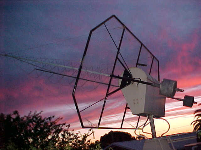
ANOTHER VIEW OF THE ANTENNA SILHOUETTED AGAINST THE EVENING SKY A view of the Head with the antenna's, reflector and counterweights showing . Note the crossed Yagi on 70cm. and the Helix on 2m. I did have a crossed Yagi on 2m. however I found that the helix gave less fading on AO-13 although I don't think that the overall gain was as great. |